Electronic Components of Satellites behave differently in outer space as compared to how these behave at sea level. How do you know that your satellite will survive outer space? How do you confirm that your circuit boards will function properly at higher altitudes? There is only one way to find out, and that is to test and validate your design.
Electronic components are part of every satellite. Even Sputnik, the first satellite in space, had electronic components, such a transponder, etc... Electrical circuits create heat during operation this happens because electrons travel through electrical conductors which create friction which in turn create heat. The heat created by any electrical circuit quickly dissipates through convection. Convection is the heat transfer due to bulk movement of molecules such as liquids or gasses.
We take convective cooling for granted here on earth. However, convection is almost non-existent at higher altitudes. As the altitude increases, the air pressure decreases. Air pressure decreases because less air molecules are present. Less air molecules means less heat can escape through convection. Hence other cooling system and methods have to be developed and tested in order to keep the electronics running. Many electronic components on a satellite will only properly function if they are maintained within a specified temperature range.
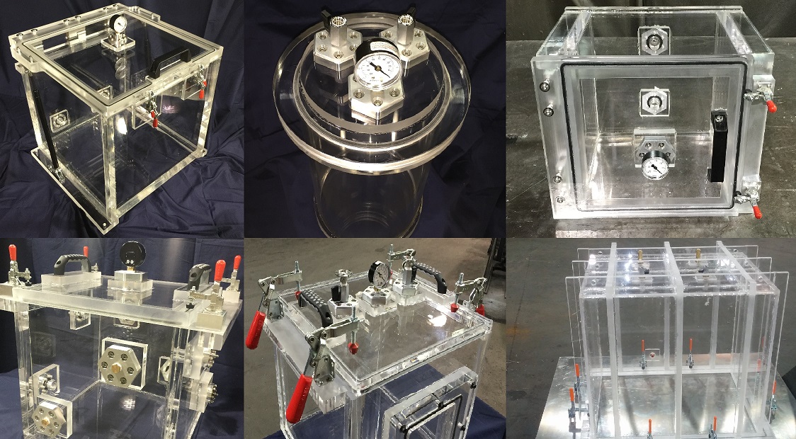
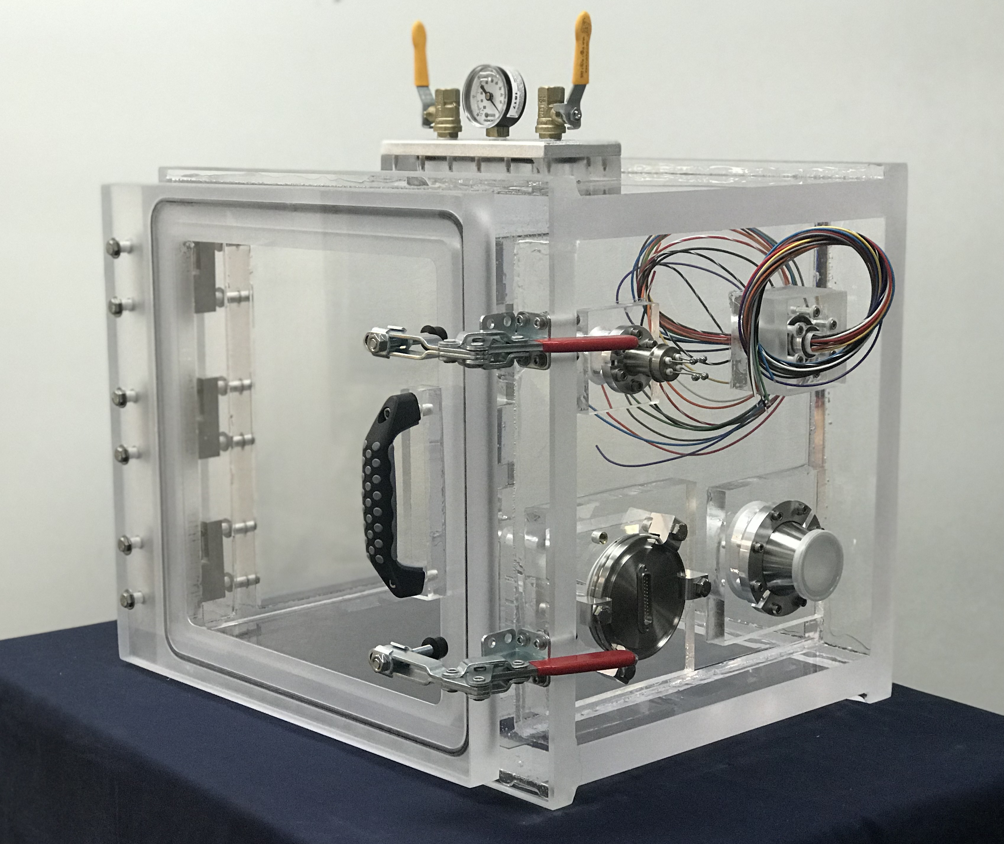
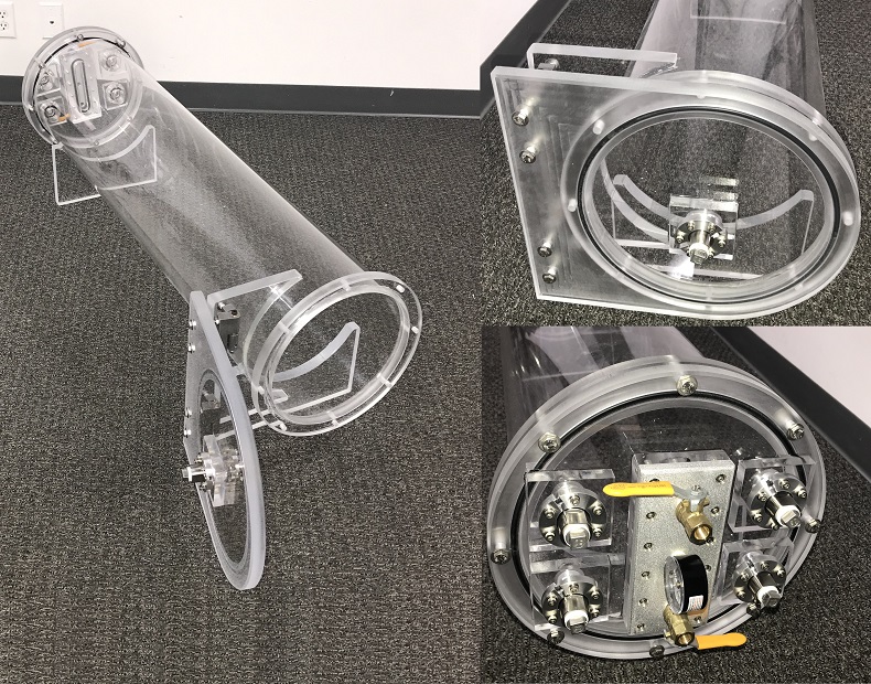
We were exited to have been contacted by one of the developers of Cube Sat asking for our help on testing their Satellite components. What you are looking at is a clear acrylic vacuum chamber, 14 inch inside dimensions, hinged side door, front loading. This chamber can be placed on a table top and accessed by opening the front door.
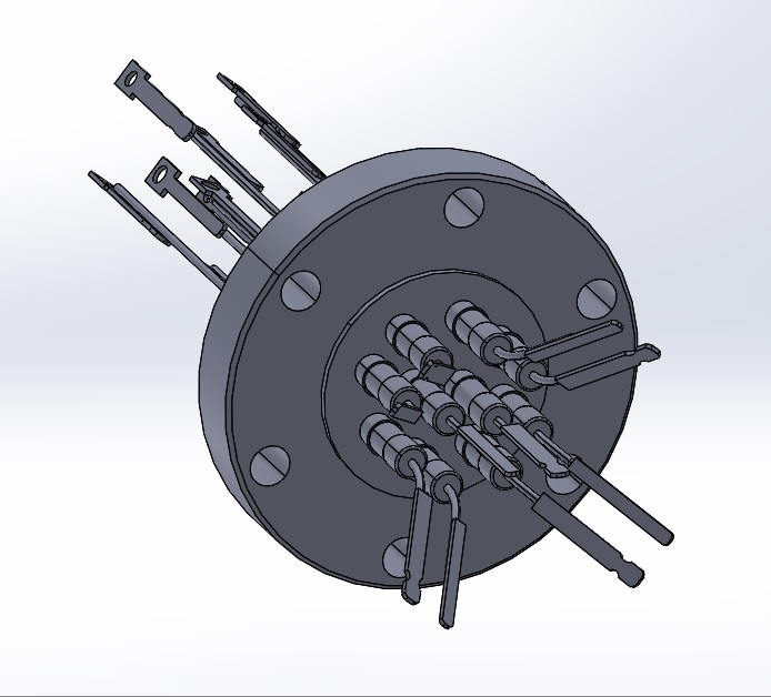
However, this vacuum chamber is different from our standard built vacuum chambers. This chamber has the vacuum valve, the venting valve, the vacuum gauge moved to the top wall. Conversely, a Two-Pair, Type J, Thermocouple Vacuum Feedthrough is placed on top left corner of the side wall. An 12 wire, 18 Gauge Vacuum Feedthrough has been placed on the top right corner of the side wall. A Multipin, 25 pin is present on the lower left corner. Finally, an NW40 Port is located on the lower right corner. This NW40 port is used to connect a high vacuum pump that will generate a vacuum high enough in order to simulate the absolute pressures of Low Earth Orbit.
While the chamber is under Vacuum, Cube Sats will be placed inside for testing. Electrical connections are run from the outside and connected to the CubeSat inside. This is possible because these Electrical Vacuum Feedthroughs are specially built components what allow the user to connect to the CubeSat from the outside without compromising the vacuum.
If you have a need for a custom vacuum chamber with Vacuum Feedthroughs, feel free to Contact Us anytime.
Similar Items
Our clients prefer to work with us because we are Experts in Custom Fabrication (especially Polymer Fabrication). Check out some of our other items we carry that you can combine/integrate with your systems or projects.
Complete List of Articles Related to Acrylic Vacuum Chambers